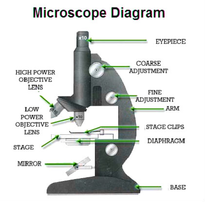

Microscope diagram below depicts parts of a typical light or optical microscope. Microscope uses lenses and light to optically increase the size of an image of whatever is being magnified. This is achieved through a magnifying glass, which varies in magnification and quality. Other parts of a microscope include eyepiece lens, tube, arm, base, illuminator, stage, rack stop, nosepiece and a diaphragm. Lets discuss each component in more detail.
The Base is the bottom of the microscope. Arms support the tube and are attached to the base. The tube is what integrates the objective lenses to the eyepiece lens. The latter is what a user sees through and is located at the top of the microscope. There are multiple objective lenses in a microscope that come in a variety of magnification powers. The final magnification is a multiple of the eyepiece lens and the objective lens (e.g. 10x eyepiece multiplied by 40x objective gives you 400x magnification). The lens with the lowest magnification are called short and with the highest are referred to as long. The objective lenses are switched with a revolving nosepiece also called a turret. the relevant proximity of these lenses to the slide is adjusted by the rack stop.
Illuminator is the the source of light or a mirror. The mirror microscope uses light from outside to display the image. The light comes from bottom of the stage, which is a platform where slides are inserted between stage clips.
How to Focus a Microscope:
1) Start with the lowest power objective lens.
2) Put the lens down close to the slide.
3) View through the eyepiece and focus upward until the image is sharp.
4) Switch objective lenses for greater magnification while adjusting the focus knob.
Microscope Diagram